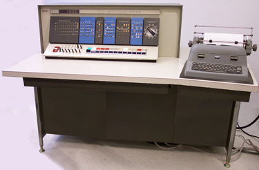
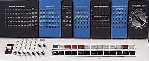
First available in 1959, the IBM 1620 was a low-cost solid state computer designed for decimal scientific and engineering calculations. The main memory was logically arranged as 20,000 6-bit words. Each word comprised four BCD data bits, a "flag" bit, and an odd parity check bit. Though this was its logical arrangement, physically memory was a 100x100 array of 12-bit ferrite core words, which causes a few quirks in the instruction set. All instructions occupied 12 consecutive digits of memory, and were required to start at an even address so that the 2-digit opcode could be read in one 12-bit physical word.
Instructions processed data memory-to-memory either in an arithmetic 'field' mode or a 'record' mode. A field of decimal integer data occupied succesive memory locations, one memory word per digit, with the most significant digit in the lowest address and the least significant digit in the highest address of the 'field'. Arithmetic instructions, such as add and subtract, processed fields by referring by the address of the least significant digit, where processing started, progressing to most significant digits in lower value addresses ('right' to 'left'). The flag bit must be set in the most significant digit to indicate the end of the field. In addition, a flag bit in the least significant digit was used to indicate a negative ingeger. Arithmetic fields were limited in length only by the size of memory.
On the other hand, Instructions that process memory as records, such as I/O operations, refered to a record with the lowest address where processing started, progressing to higher addresses ('left' to 'right'). The end of a record was indicated by a special invalid BCD bit combination of 0xA called a 'record mark'. I/O processing was either in numeric mode with one numeric character per memory word, or 'alphameric' mode where two consecutive memory digits encode the alphanumeric character set associated with Hollerith cards. Similar to instruction opcodes, the two digit alphameric character codes also were required to start at even addresses.
With the option of indirect addressing, the memory address in any instruction may have the flag bit in the least significant digit set to indicate indirection. This address then was assumed to refer to the least significant (highest address value) word of a 5-digit field containing the actual address to use. However, that address may be indirect as well with a flag in its least significant digit, and addressing can be indirect to arbitrary levels. No flag bit is required in the most significant digit of indirect address fields, as they were assumed to be of a fixed 5 digits in length.
Subroutines were accomodated by a special register that stored the return address in the main calling program. There was no access to this register other than with the 'Branch Back' instruction that transfered control back to the calling program. Therefore there was no hardware support for more than one level of subroutine. However the subroutine call instruction, 'Branch and Transmit' not only stored the return address but also copied a field of argument data to a parameter area in descending memory addresses just lower than the instructions of the subroutine. Although this mechanism was intended to provide the subroutine its variable argument data, a return address could also be transmitted as well and therefore multiple levels of subroutines, or even push-pop stacks for local variables, could be manually coded.
Although magnetic disk peripherals became available for the 1620 later in the 1960's, initial low cost systems used only paper tape or punched cards for secondary storage, and a console keyboard and teletypewriter for I/O.
| Instruction | Mnemonic | Decimal | Action |
|---|---|---|---|
| Add | A | 21PPPPPQQQQQ | Add field at address QQQQQ to field at address PPPPP and set arithmetic indicators |
| Add Immediate | AM | 11PPPPPDDDDD | Add field DDDDD to field at address PPPPP and set arithmetic indicators |
| Branch | B | 49PPPPPXXXXX | Branch to address PPPPP |
| Branch and Transmit | BT | 27PPPPPQQQQQ | Copy field at address QQQQQ to address PPPPP-1, store address of next instruction in IR-2 register and branch to address PPPPP |
| Branch and Transmit Immediate | BTM | 17PPPPPDDDDD | Copy field DDDDD to address PPPPP-1, store address of next instruction in IR-2 register and branch to address PPPPP |
| Branch Back | BB | 42XXXXXXXXXX | Branch to address stored in IR-2 register |
| Branch Indicator | BI | 46PPPPP0II00 | Branch to address PPPPP if indictor II true |
| Branch no Flag | BNF | 44PPPPPQQQQQ | Branch to address PPPPP if no flag bit set at address QQQQQ |
| Branch no Indicator | BNI | 47PPPPP0II00 | Branch to address PPPPP if indictor II false |
| Branch no Record Mark | BNR | 45PPPPPQQQQQ | Branch to address PPPPP if no record mark at address QQQQQ |
| Branch on Digit | BD | 43PPPPPQQQQQ | Branch to address PPPPP if nonzero digit at address QQQQQ |
| Clear Flag | CF | 33PPPPPXXXXX | Clear flag bit at address PPPPP |
| Compare | C | 24PPPPPQQQQQ | Subtract field at address QQQQQ from field at address PPPPP and set arithmetic indicators |
| Compare Immediate | CM | 14PPPPPDDDDD | Subtract field DDDDD from field at address PPPPP and set arithmetic indicators |
| Control | K | 34XXXXX0UU00C | Control I/O unit UU with control command C |
| Dump Numeric | DN | 35PPPPP0UU000 | Dump numerically to I/O unit UU starting from address PPPPP |
| Halt | H | 48XXXXXXXXXX | Halt execution |
| Multiply | M | 23PPPPPQQQQQ | Multiply field at address PPPPP by field at address QQQQQ and set arithmetic indicators |
| Multiply Immediate | MM | 13PPPPPDDDDD | Multiply field at address PPPPP by field DDDDD and set arithmetic indicators |
| No Operation | NOP | 41XXXXXXXXXX | No operation |
| Read Alphameric | RA | 37PPPPP0UU000 | Read alphamerically from I/O unit UU into address PPPPP |
| Read Numeric | RN | 36PPPPP0UU000 | Read numerically from I/O unit UU into address PPPPP |
| Set Flag | SF | 32PPPPPXXXXX | Set flag bit at address PPPPP |
| Subtract | S | 22PPPPPQQQQQ | Subtract field at address QQQQQ from field at address PPPPP and set arithmetic indicators |
| Subtract Immediate | SM | 12PPPPPDDDDD | Subtract field DDDDD from field at address PPPPP and set arithmetic indicators |
| Transmit Digit | TD | 25PPPPPQQQQQ | Copy digit at address QQQQQ to address PPPPP |
| Transmit Digit Immediate | TDM | 15PPPPP0000D | Copy digit D to address PPPPP |
| Transmit Field | TF | 26PPPPPQQQQQ | Copy field at address QQQQQ to address PPPPP |
| Transmit Field Immediate | TFM | 16PPPPPDDDDD | Copy field DDDDD to address PPPPP |
| Transmit Record | TR | 31PPPPPQQQQQ | Copy record at address QQQQQ to address PPPPP |
| Write Alphameric | WA | 39PPPPP0UU000 | Write alphamerically to I/O unit UU from address PPPPP |
| Write Numeric | WN | 38PPPPP0UU000 | Write numerically to I/O unit UU from address PPPPP |
PPPPP and QQQQQ are 5-digit memory addresses. Flag bit set in least
significant digit indicates indirect address.
DDDDD are 2 to 5 digit immediate data. Must have flag bit set in most
significant digit to limit the field length.
UU are I/O unit: 01=typewriter, 02=paper tape punch, 03=paper tape reader,
04=card punch, 05=card reader.
For typewriter unit, control command C is:
1=space, 2=carraige return, 8=tabulate.
II are indicators: 01=console program switch 1,
02=switch 2, 03=switch 3, 04=switch 4, 06=read check,
07=write check, 09=last card, 11=high/positive, 12=equal/zero, 13=H/P or E/Z,
14=overflow, 19=any check.
XXXXX are ignored.